Implementation
Hardware
Xiao Robotics Tank Chassis
A strong aluminum alloy chassis with dual built in 6-15-volt geared DC Motors. Attached to the motors are two hard plastic tracks that span the length of the chassis. The chassis is heavy duty and has mounting holes and a large compartment between the dual tracks.
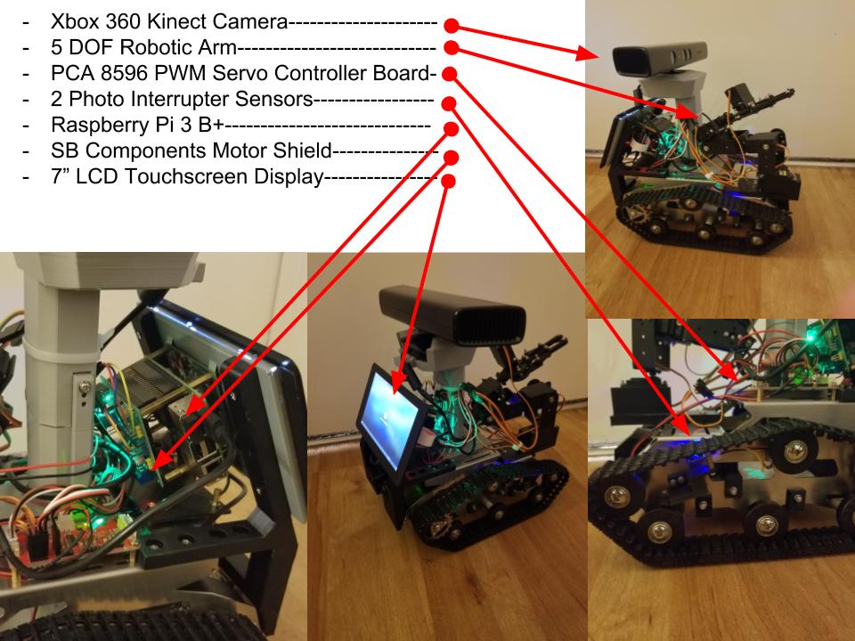
Raspberry Pi 3 B+
The Raspberry Pi 3 B+ has a 64-bit quad core processor running at 1.4 Ghz. It incorporates built-in WiFi and Bluetooth connectivity with enhanced dual-band 2.4 GHz and 5 GHz WiFi, Bluetooth 4.2/BLE and faster Ethernet.
7 “ Raspberry Pi Touchscreen
A 7” Touchscreen Display. Screen Dimensions: 194mm x 110mm x 20mm (including standoffs) Viewable screen size: 155mm x 86mm Screen Resolution 800 x 480 pixels 10 finger capacitive touch Connects to the Raspberry Pi board using a ribbon cable connected to the DSI port. Adapter board is used to power the display and convert the parallel signals from the display to the serial (DSI) port on the Raspberry Pi.
Xbox 360 Kinect
The Kinect sensor is a horizontal bar connected to a small base with a motorized pivot and is designed to be positioned lengthwise above or below the video display. The device features an “RGB camera, depth sensor and multi-array microphone running proprietary software”, which provide full-body 3D motion capture, facial recognition and voice recognition capabilities.
PCA 9685 16 channel Servo Controller
The PCA9685 is an I2C-bus controlled 16-channel LED controller optimized for Red/Green/Blue/Amber (RGBA) color backlighting applications. Each LED output has its own 12-bit resolution (4096 steps) fixed frequency individual PWM controller that operates at a programmable frequency from a typical of 24 Hz to 1526 Hz with a duty cycle that is adjustable from 0 % to 100 % to allow the LED to be set to a specific brightness value.
Mg966r 4.8V-7.2V Servo Motor
This High-Torque MG996R Digital Servo features metal gearing resulting in extra high 10kg stalling torque in a tiny package. The MG996R features upgraded shock-proofing and a redesigned PCB and IC control system that make it much more accurate. The gearing and motor have also been upgraded to improve dead bandwidth and centering. The unit comes complete with 30cm wire and 3 pin ‘S’ type female header connector that fits most receivers.
SunFounder Photo-interrupter Sensor Module
A photo-interrupter is a sensor that arranges light-emitting component and light-receiving component face-to-face and packages them together. It applies the principle that light is interrupted when an object passes through the sensor. Therefore, photo-interrupters are widely used in many fields like speed measurement.
Custom Made Parts
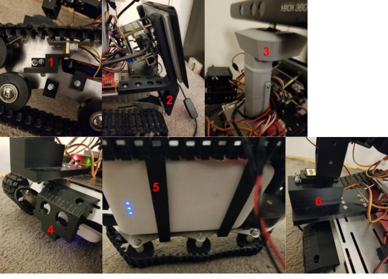
- Specially measured and 3d printed mount for the photo Interrupters.
- Specially designed mounts for the Raspberry Pi touchscreen.
- Specially designed mount and offset for the Xbox 360 Kinect.
- Specially designed front battery holder designed to also mount a ultrasonic sensor if desired.
- Specially designed battery holders on the bottom of the robot.
- 3d Printed arm mount designed to add a fifth servo for increased mobility.
Software
Software We Downloaded
To make our robot functional, we had to work with a variety of software. First, we had to install ROS kinetic on the robot’s Raspberry Pi, so that we could work with ROS packages. For debugging purposes, we also decided to set up a laptop with RVIZ. We configured the laptop and the Pi so that the laptop could see the ROS topics being published on the pi, and visualize them in RVIZ. We also configured the laptop to be able to SSH into the Pi so that it was easier to make small changes to files on the Pi. The open source ROS packages we used were freenect_stack, libfreenect, rgbd_launch, and ar_track_alvar. We used freenect_stack, libfreenect, and rgbd_launch to make the Xbox 360 Kinect function properly in ROS, and Ar_track_alvar for AR tag recognition. We also downloaded a python file called PiMotor, which is used to send input values to the robots wheel motors so the robot can move.
Software We Wrote
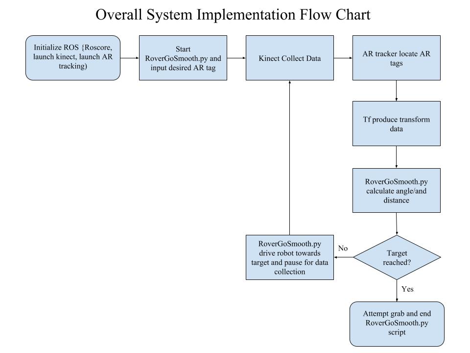
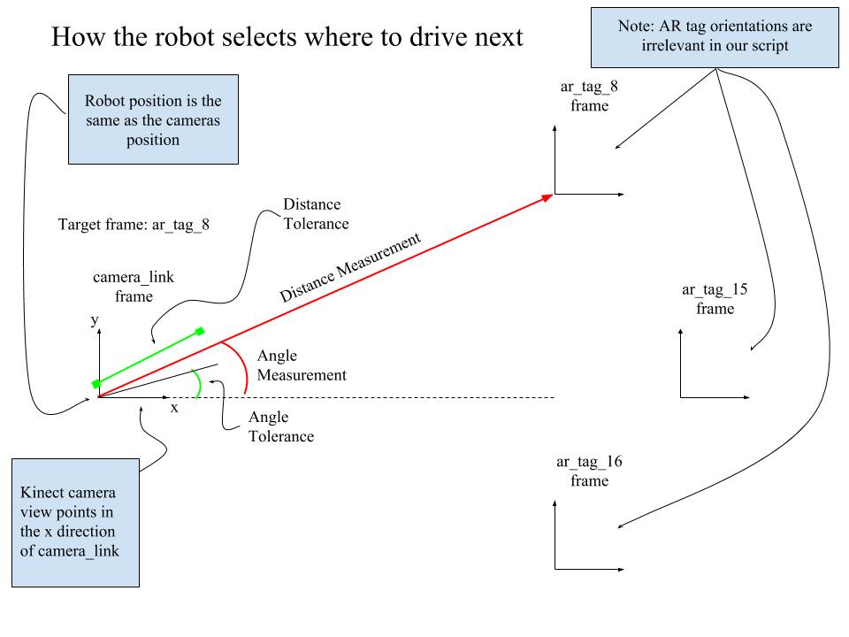
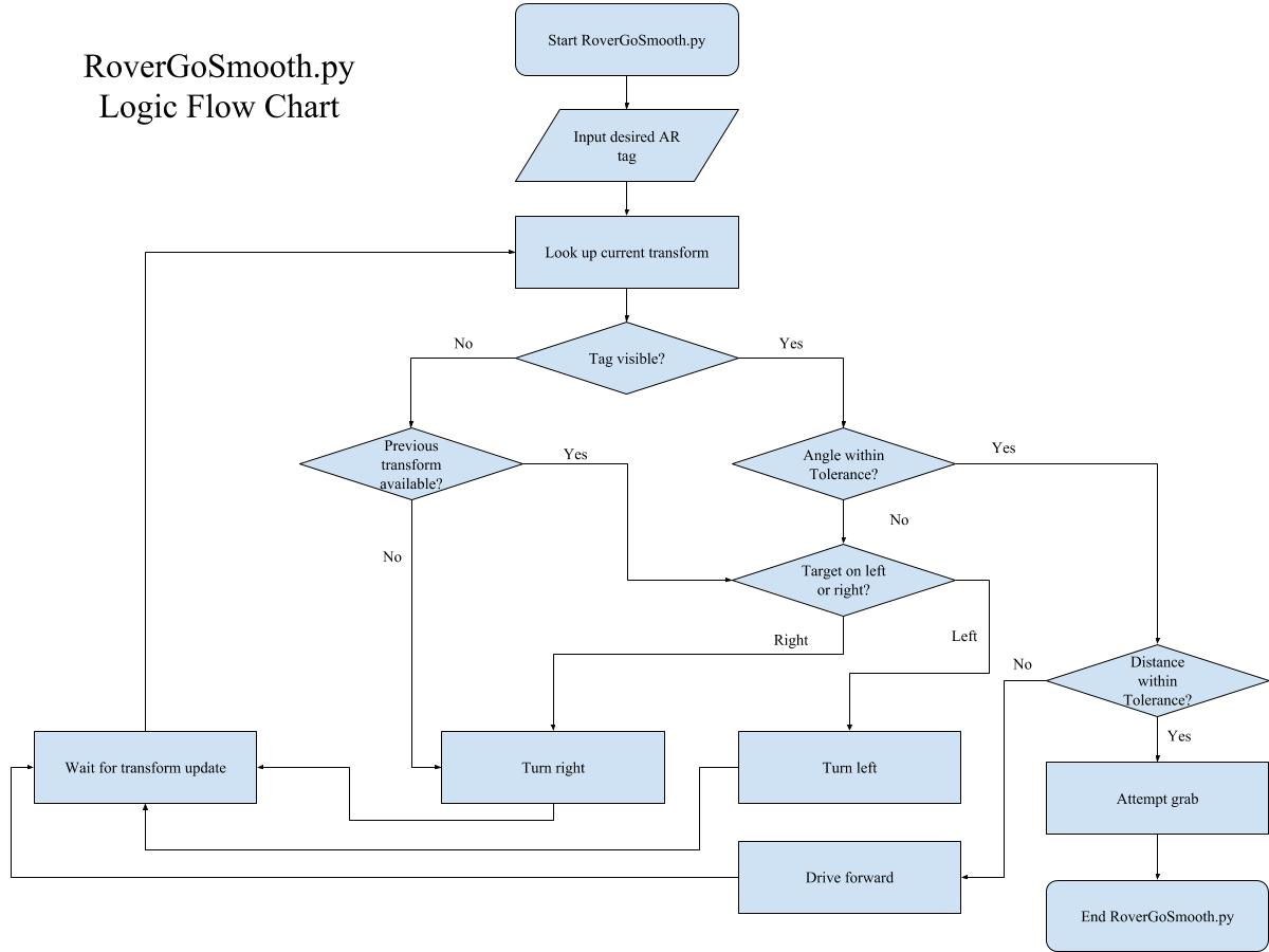
To actually drive the robot, we wrote a python script called RoverGoSmooth.py. After starting a roscore and launching the aforementioned packages necessary to run the kinect and AR tracking, RoverGoSmooth.py can be ran in a new terminal to activate the robot. A script will prompt the user for the desired AR-tag destination and then the robot will drive to its target and attempt to grab the object located near that target. RoverGoSmooth.py works by using a tf transform listener to repeatedly look up the most recent transformation to the target AR-tag The robot then uses this information to make a decision about where to drive next, and drives in that direction for a short burst. When the robot is finished driving for that particular step, it pauses for a short time period to allow ar_track_alvar to update its information about the AR-tags. If the tag is not visible when the robot is started, the robot will periodically make small turns in a circle and essentially “search” for the AR-tag. Once the tag is visible, the translation data from the tf transform is used to compute the distance to the tag, as well as an angle that represents how far off center the tag is within the robots current field of view.
Transforms are computed relative the the Kinect frame, camera_link. This frame is convenient to use because the x-axis of the frame always points in the same direction as the camera’s lense. The distance is computed via a simple 2 dimensional distance formula (z direction is not relevant for driving in the x-y plane). The angle is simple the angle offset of the target AR-tag relative to the camera_link frames x-axis, where an angle of zero tells the robot that the target is straight ahead. At each driving step, the robot computes this distance and angle and makes a decision. First, the robot checks if the tag is within a given angle tolerance, if it is not, it uses the sign of the computed angle to decide to turn left or right. If the angle is within tolerance, the robot then checks to see if the robot is within a given distance tolerance. If it is not, the robot drives forward. Otherwise the robot will attempt a grab via another python script we wrote, grabBlock.py.
When the robot is actually moving, it needs to either drive straight or turn accurately. To accomplish this, we implemented a very simple proportional controller that uses photo interrupters to compute approximately how far each wheel has turned. The controller then attempts to adjust the input of one wheel while holding the other input constant so that the two wheels always travel an equal distance so that the robot can drive straight. Note that because the robot drives in short bursts, this controller is mostly a safeguard, as the most important aspect for getting our robot to drive straight was calibrating the initial inputs to the wheels so that it at least starts off driving straight initially. Calibrating these inputs was done simply by trial and error.
We also included some logic that prompts the robot to search for the target again if it loses sight of the tag while driving. The most recent previous known location of the tag is used to attempt to make an accurate choice about which direction to turn in this case. This python script could have been turned into an actual ROS node, but given how it functions we felt that this was unnecessary and overly complicated, so we decided to just keep it as a simple python script. The other script that we wrote, grabBlock.py applies inputs to the robot arm that causes it to reach out in front of the robot and attempt a grab. This code for this script is simply a sequence of hard coded inputs to the arm that causes the robot to attempt to grab whatever is currently in front of it.
System Overview
Overall, our system works by continuously using the Kinect to collect image data. Ar_track_alvar then takes this data and computes which AR tags are visible. Tf then computes the transformations to each of the tags. While this is all happening, RoverGoSmooth.py can be ran with a particular AR tag selection. RoverGoSmooth.py then periodically looks up the transformation to the desired AR tag and makes a decision about which direction to move in. Once the robot is within the desired distance and angle tolerances relative to its desired AR tag, the attempts to grab the object at the AR tag via grabBlock.py